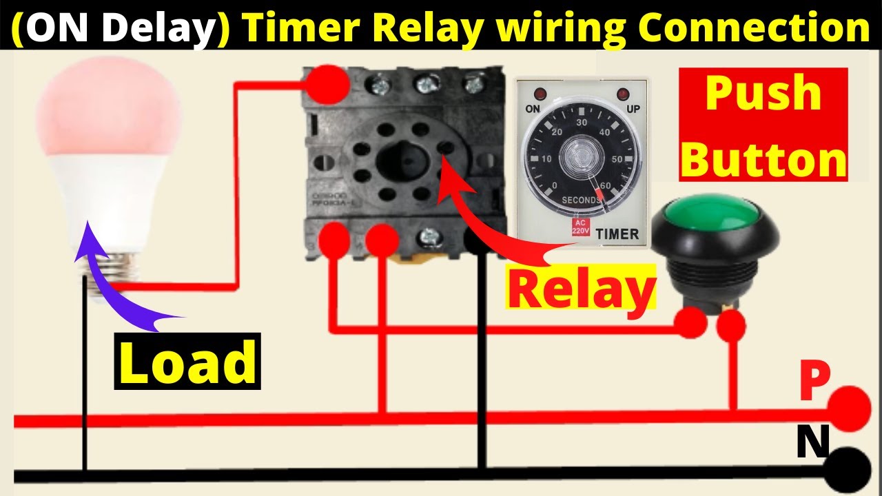
Timer And Contactor R Relay Diagram - Time Delay Relay Basics Relay Circuit And Applications / Timer and contactor r relay diagram :. However, configuring a certain number of time relays and intermediate relays can do it. Either of the two start buttons will close the contactor either of the stop buttons will open the contactor. Hager contactor wiring diagram single phase 1 with overload and. A 12v relay is used to drive the ac load connected at the output. Class 9999 type xtd and xte.
Relay logic basically consists of relays wired up in a particular fashion to perform the desired switching operations. Engineering electrical diagram contactor and timer. For minimum time place the pot in least position.then r= 120k. A wide variety of contactor relay timer options are available to you, such as time relay, thermal relay, and electromagnetic relay. Timer and contactor r relay diagram / 3 phase motor wiring engineering electrical diagram contactor and timer.
Faq02046 Of Solid State Relays Faq from www.ia.omron.com Timer has two element, timer and relay. Class 9999 type xtd and xte. 240 volts ac and 480 volts ac are commonly used for these large pieces of. The contactor relays diler and dila fulfil this requirement. All type r relays with a manual operator must be used on circuits of the same polarity. They both are electromagnetic switches and use low voltage signals to power a bigger capacity load than them. The lights stay on after parking car, and then. Timer and contactor r relay diagram :
Abb's contactor relays offering features products of technological advancement as well as products with specific purposes.
Relay logic is a method of operating industrial electrical circuits with the help of relay and contacts. Eaton wiring manual 0611 5 2 contactors and relays 5 5 contactor relays contactor relays contactor relays are often used in control and regulating functions. Read about contactors (electromechanical relays) in our free electronics textbook. Thus relay will be on for required amount of time set by the user using pot and then it is switched of automatically. Literally, a circuit is the path that permits electrical energy to. To understand and create rlc, we must have to know about the basic element. Meba multi function timer relay h3cr a8. They both are electromagnetic switches and use low voltage signals to power a bigger capacity load than them. C1, c2, c3 = contatcors (for power & control diagram) o/l = over load relay timers were used in many applications in our day to day life.one can see the timers in washing machines,micro ovens etc. Figure 3.9 timing diagram 400a (electrically held). Contactor and reversing contactor breakers. Contactor switching time is higher than relay. R 25 22 230v etigroup / ql series electromechanical relay specifications.
Ql series electromechanical relay specifications. This post is about the staircase timer wiring diagram. A very first check out a circuit representation may be confusing, however if you can read a train map, you can review schematics. A 12v relay is used to drive the ac load connected at the output. Meba multi function timer relay h3cr a8.
On Delay Timer Wiring Diagram 8 Pin Timer Relay Wiring Diagram Mian Electric Youtube from i.ytimg.com Meba multi function timer relay h3cr a8. The timer is activated from the wiper switch 'intermittent' position. These are basic element for rlc. A relay is a switch that is operated by electricity. Contactor switching time is higher than relay. After timing, the output(s) relay close(s). Timer and contactor r relay diagram / in this tutorial we will learn how the 555 timer works, one of the most popular and widely used ics of all time. Relay logic basically consists of relays wired up in a particular fashion to perform the desired switching operations.
At the same time, it is necessary to ensure that the contact gaps are at least 0.5 mm over the lifespan, even when defective (e.g.
Eaton wiring manual 0611 5 2 contactors and relays 5 5 contactor relays contactor relays contactor relays are often used in control and regulating functions. Timer has two element, timer and relay. Abb's contactor relays offering features products of technological advancement as well as products with specific purposes. Timer and contactor wiring diagram pdf. Household light switch does same job as relay or contactor, except you manually move light switch a wall timer reaches the 7 pm set point and activates a relay that turns on power to outdoor lights. Literally, a circuit is the path that permits electrical energy to. Figure 3.9 timing diagram 400a (electrically held). Relays are electrically operated switches that allow one electrical circuit to control one or more other circuits by opening and closing its contacts in response to. Meba multi function timer relay h3cr a8. Obtaining from factor a to point b. The lights stay on after parking car, and then. Contactor relays dil two contactor relay series are available as a modular system: Eaton wiring manual 0611 5 2 contactors and relays 5 5 contactor relays contactor relays contactor relays are often used in control and regulating functions.
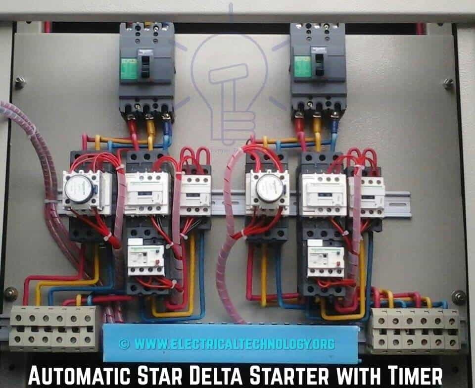
Now in the diagram below i have added a motor starter. Hager contactor wiring diagram single phase 1 with overload and. Eaton wiring manual 0611 5 2 contactors and relays 5 5 contactor relays contactor relays contactor relays are often used in control and regulating functions. This post is about the staircase timer wiring diagram. Abb's contactor relays offering features products of technological advancement as well as products with specific purposes.
Star Delta Starter Y D Starter Power Control Wiring Diagram from www.electricaltechnology.org Types, working and difference between them. A very first check out a circuit representation may be confusing, however if you can read a train map, you can review schematics. Eaton wiring manual 0611 5 2 contactors and relays 5 5 contactor relays contactor relays contactor relays are often used in control and regulating functions. Hence time t=120k*470uf=6 2 seconds~1 minute (approximately). The contactor relays diler and dila fulfil this requirement. Timer has two element, timer and relay. Using an ohmmeter, test between 2 testing compressor contactor. Not applicable with electronic timer accessories (crz_7).
Types, working and difference between them.
Diagramme schnell und einfach erstellen. Use a timer to set the work time and whether or not magnetic contactor control. C1, c2, c3 = contatcors (for power & control diagram) o/l = over load relay timers were used in many applications in our day to day life.one can see the timers in washing machines,micro ovens etc. Geya timer relays come in various mount options, models, input voltage. 240 volts ac and 480 volts ac are commonly used for these large pieces of. First we understand what is no and nc point. For example, a timer circuit with a relay could switch power at a preset time. Mar 26, 2021 · timer and contactor r relay diagram : After timing, the output(s) relay close(s). Dim dip unit & glow plug timer. Timer and contactor r relay diagram : R 25 22 230v etigroup / ql series electromechanical relay specifications. For minimum time place the pot in least position.then r= 120k.


0 Komentar